A very productive day today. The plan was to complete the matchdrilling and preparation of parts today on the right elevator and we succeeded in completing all steps in the plan.
Edge preparing was completed in the previous days. Jacques came over to give me a hand.
Work starts with matchdrilling the reinforcement plates to the rear spar.Cleco and drilling the E610PP and E611PP in place on the E702.
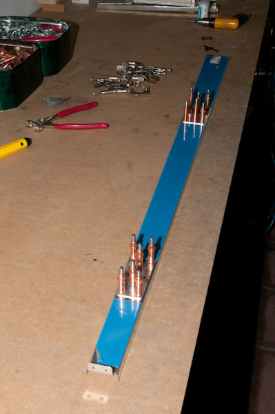
Then prepare the edges of E703 and E704 by fluting. Flanges rest nicely against the table. All straight and ready to be matched up.

Cleco the two of them together and drill them to #30.
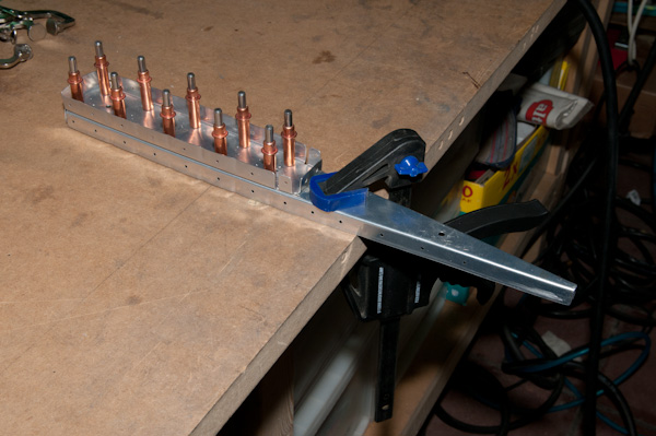
Then attach the assembly to the rear spar E702. And this is where the misery starts with this frame. As you can see in the picture below. Once they are connected, the flanges at the intersection of E704 and E702 don't align well although the parts butt together.
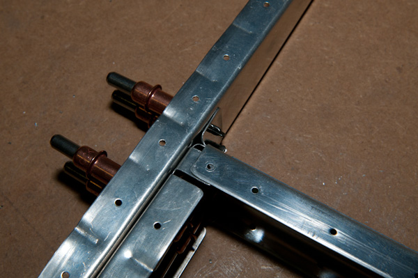
With a little effort, you get them aligned (kind of forcing things) and then it's time to prepare the lead counterweight E714.
On the right elevator - and ONLY on the right elevator - the plan calls for cutting away a part of the lead block.
In the meanwhile, I figured out why this is.
The trim tab and some extra ribs bring some extra weight to the left elevator. To compensate for this and to allow better balance, the lead block on the right one should be lighter then the left one.
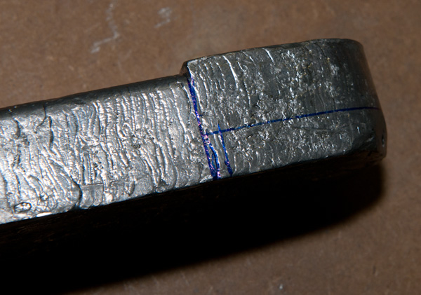
Used the drill press for the drilling, then the band saw for cutting the lead away. Bad idea. 1. It doens't cut well and 2. I broke the saw.
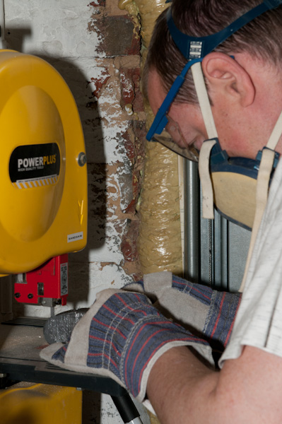
I then finished it off with the vixen file and some smaller metal files
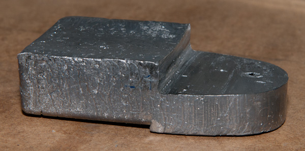
Now attach the E714counterweight to the previous assembly of E703 and E704 and add the counterweight skin E713 over it.
This is the most miserable part because the prepunched holes on the skins are off by half a diameter. I have seen this remark on many websites.
I managed to somehow make it work by working the flanges on E703 and E704 but still it is a tight fit.
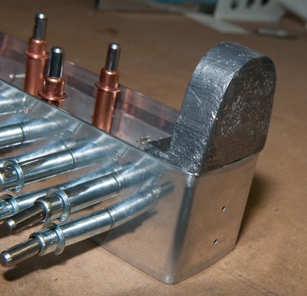
In the end, the clecoes are forced in but you can clearly see in the picture that the clecoes are under a lot of stress.
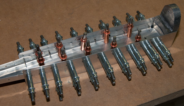
The step in the lead block should butt against the counterweight skin. The E714 must be slightly bend over the counterweight eventually taking away material from the lead counterweight.
Now i's time to drill the #10 hole through the pilot holes in the front of the counterweight skin. I first drilled through with a #40 drill.
It's diffictult to do this in a bench drill. If you do it manually, make sure you have a second pair of eyes that look at the angle of how you hold the dril and make sure the assembly is fixed with a grip.
You should have a perfect 90° angle to the material or you will misalign on the other side !
That was also part of the reason of first drilling #40.
Once finished that hole, enlarged to #30 until halfway in and then final with #10.
Use lot's of tapping oil , boelube when drilling in the lead. It's a terrible metal that clogs the drill constantly.
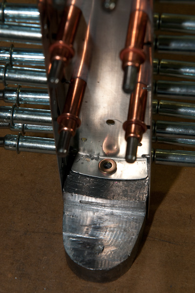
Both holes turned out very good. The picture below shows the clearence of the AN960-10 washer from the web of the E703 rib.
I then did something stupid. (As usual)
Nothing being 100% happy with the hole because the screw went in a little hard, I went through the hole again with the#10.
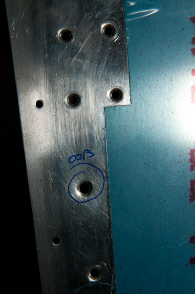
By doing so, I made the hole in the flange of the E703 rib oval !!!! DAMN !!!
It's not dramatic, but I was thinking of my good friend Fred's words : 'if you do something twice or try to make it better, the result will always be worse'.
He's right, but I'm just hard school and always make the same stupid mistakes.
Next step, add the E709 rib on the other end of the skeleton and cleco the entire substructure to the E701R skin.
Matchdrill the rib to the rear spar. Attention here, these holes need to be #40 for 3/32" rivets. Usually the attach rivet of the skeleton are 1/8" but in this special case, it's 3/32"
The reason for that is that the elevator attach horn will sit over this joint and these will be flush AN426 rivets that will sit in a countersink not to obstruct with the WD605R-1 attach horn
Then, attach the elevator attach horn to the assembly and match drill it.
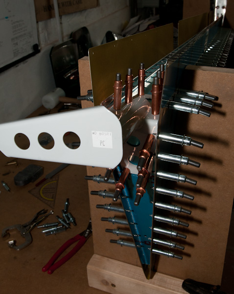
Then matchdrill all holes of the skin to the substructure #40 size. The last two holes on the narrow end of each rib will be drilled through using the skin as drill guide.
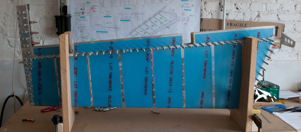
Everything is drilled now. From here on we will disassemble the hole structure again and proceed with deburring all drill holes.
The connection of E709 with E702 needs to be machine countersunk.(E702 front side).
The middle two holes can be machine countersunk using the countersink cage. The outer 2 are problematic and have to be done manually.
I replaced the #40 countersink bit in the manual deburr tool and started manually countersinking the drilled hole.
Little bit at a time, checking regularily for depth and form of the countersink.
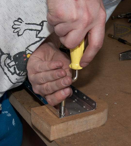
The result of the countersinking. The manual ones look nearly as good as the machine countersunk ones.

Also machine countersink #12 of the E 714 counterweight holes on the front side. Dimple #12 the counterweight skin.
I used the vise dimplers for this.
Then proceed with dimpling the rest of the spars, ribs and skin.
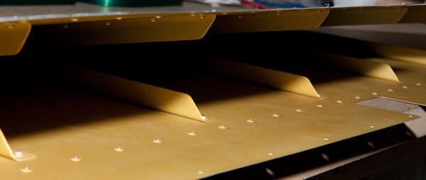
I used the pneumatic squeezer to dimple the skins and ribs. Very nice and less effort but got near disaster again.
By the end of the first side, the skin shifted a little while squeezing and I got a nasty misaligned dimple out of the radius of the hole.
I decided not to panic and immediatly go for the oops-rivet solution.
I enlarged the hole to #30 and dimpled it again. You will not see the difference once it is rivetted but once again, it shows that getting tired and long repetitive work makes you prone for error.
Don't let your kids come near of your workshop if you want a decent education.
After a lot of swearing and cursing and using words you didn't even realize you knew them, the patched result looks decent.
