
TitleGarrison
“No bird ever flew nonstop from New York to Tokyo, or raced 15 miles high at triple the speed of sound.
But birds do something else.
They do not conquer the air; they romance it..”
Peter Garrison
HoursAndCounting
Jur's RV7 Aircraft Factory
2917 hours and counting
Some decisions in life are bare of any obvious logic
Control Surface
Control Surface Final 27/12/2010
Another 8 hours of experimenting with basic techniques. I managed to finalise the control surface project in a total of almost 15 hours.
The day started with disassembling the clecoed assembly where I left of yesterday. First deburring all drilled holes. Then dimpled the skins to 3/32 with the c-frame.
Then dimpled the ribs using the handsqueezer. The ribs worked fine. Then I dimpled the spar. The spar is 0.04 aluminum and is hard to dimple. At first sight, the dimple works fine and the rivet seems to fit in.

However, later on when I assembled the pieces together again, it seemed that the rivet was not even with the skin surface. Next lesson learned: follow the advices on the instructions in the plan. The plan says to dimple the 0.04, then use the hand deburring tool to manually countersink by eye. After doing this, the rivets where nice and flush.
Then I countersunk the trailing edge and the two corner intersections on the spar where the rib, skin and spar connect. You can safely countersink the spar here as is lays interlocked between skin and rib (according to the manual).

skins dimpled

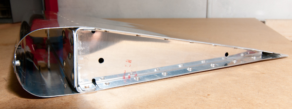
The manual advices to make a small fixture to facilitate the working process while rivetting. In the image below, the project is attached to the jig and I just finished rivetting the 3-3.5 flush rivets. For some reason these did not go well in the beginning.
I was not pleased with 2 of them so I drilled them out and did it all over again.

Then it's time to put the second skin on and that is where the first misery of the day started. To rivet the other side, you have to stretch the already rivetted bottom skin and manage to hold the bukking bar in between. It worked in the end but a lot of time went by just to try to get the right grip. It's also more difficult to measure the rivets to check the correct setting so I may need to get that little mirror after all.
The picture below is how it looks like with both skins rivetted on the spar.

The next step was setting the 3-3 rivets on the ribs. This was done with the hand squeezer and my small rivet yoke. (thanks David for the good advice to buy this right away) .
Squeezing these was like a walk in the park. Real fun to do and always resulting in a nicely set rivet head.
The last rivet near the narrow end of the rib was a bit of a pain. I managed to use the squeezer on one end. But the other end did not give enough clearnence. I used the backrivetting technique as shown on the eaa side but still I found it very difficult. (Maybe I have to buy a smaller steel plate for this next time). Once it was set half way, I managed to get te squeezer on and it set perfectly in the end.
Then came the rivetting of the trailing edge. This is done with the 3-3 rivets set on de backriver plate Then backrivet them with the mushroom flush head right on the rivet. I thought this would be difficult but it seemed to beone of the most easy things to do on the entire project. You cannot really overdrill these as they form in the dimple. The only difficulty is that the trailing edge has to remain straight during this process. I guess this is even more try with a large version of this control surface.
What is still unclear is to find out what to do if it is not straight. The manual doesn't give any advice for this.
Once the rivetting is done, it's time for the bending of the leading edges. I think this was the most difficult part of the training project. I executed the actions as in the manual using a 1inch pipe and duct tape and forming the bend by putting backpressure on the pipe and litterally rolling the aluminum on the pipe avoiding that it bends near the spar. This worked reasonably well.
Before doing the bending I had used the roller tool to make a small bend in the edge of the overlapping skin. Off course I did this too lightly so that once I put the skins together, it showed some nasty gaps between the places where the rivets would end.
Once the aluminum is bend... it is impossible to use the edge roller tool again so I had a bit of a problem. I drilled the holes in both skins and clecoed together. Then uncoupled them and started bending the last bit of the edge using a small cleco clamp (sounds funny I know, but I really tried with a lot of other stuff. The edge straigthen vise didn't work). Making small bends near the end, and trying numeruous times, I finally managed to make some nice fits between the two skins. showing no gaps. Next time, I really need to make a nice bend before bending the skins !
Once that was done, it was a piece of cake to pull the pop rivets in place.
Here is the final product.


Mistakes made:
- Drill dents (visible in the picture) near 4th rivet from trailing edge on bottom stiffener
- I may have oversized a hole in the spar when drilling out one rivet. Drilling out rivets is something I'll have to practice.
- Not enough bending on the leading edge of the top skin
- 0.5 mm alignment difference in bend joint between top and bottom skin probably by bending difference between top and bottom skin
- small gaps between rib flange and spar after setting rivet. Rib sits straight agains spar but tips of small flanges curl after rivetting. small but beauty error
- Don't drill in your fingers ! It's stupid... I did...
I feel more confident about starting on the real thing then I did some days ago. Some attention points to work on but I think I mastered the basic techniques. It wouldn't be bad if someone could comment on my rivet sizes.
Control surface part2 26/12/2010
The control surface project continues. Worked 7 hours today.
First job after cutting the stiffereners is deburrig all the components. I use the deburr knife twice per side. This gives the sides allready a safe edge. Hower I can not resist very lightly polishing it afterwards on the scotchbrite wheel.
It gives the aluminum that nice and shiny look. I removed the plastic using a soldering iron as shown in many instruction video's and found out it works quite well.
It's easy to remove the plastic and it does not leave marks on the material. In the next picture, the sides are deburred, the plastic top and bottom side removed to allow the stiffereners to be placed and clecoed.

Next step is dimpling the skins and stiffeners with the 3/32 dimplie dies. I used the C-Frame. The skins require just some very light taps. Don't overdo this or you end up with an enlarged whole or a too deep dimple.
As an exercise, I'm trying to keep the plastic protection on as long as possible.

The plans call out for back rivetting the stiffeners to the skin. Pay special attention to the direction of the stiffeners, there are right side and left side stiffeners. Best here seriously think about it once, and then mark the material with a marking pen.
The backrivetting of 3-3 rivets is starting to go well. Better then the first time. I can only confirm what the video's say, rivetting is not exact science, it is an art. Certainly these small ones are easily over-set. To make sure about the quality of my rivets, I started calculating how much the 1.5 diameter actually is and used the caliper to measure my offset. It turns out that I'm doing fine. When the rivet fills the diameter whole of the rivet gauge, it is actually perfectly set. It is also a matter of calibrating your eye. I'm starting to get to the point where I can more or less see what the quality of my rivet is. I guess that is what these training projects are all about: getting used to the material and learning by experience.
The next construction step is building the skelecton. I clecoed the ribs, spar and reinforcement plates together and back drilled the spar and remaining holes in the reinforcement plate.

Then after deburring the holes, It's rivetting time again. The ribs and reinforcement plate are riveted with solid rivets 4-4.
The rivetting went fine but I noticed some inperfections here on the side of the rib flange. You can see in the picture below that the aluminym of the rib flange curls up a bit as the rivet sets near the end.
I drilled out the rivets and started all over, first prebending lightly the flange but I ended up with the same result. If someone can confirm this is normal, I would feel a lot better.

The end of a days work. The skins clecoed and matchdrilled to the ribs. The skin matchdrilled to the spar and the trailing wedge inserted and drilled at 86° angle.

Control surface start 25/12/2010
Working on Christmas day...
Here is the content of the control surface pack.

The control surface requires first to cut the stiffeners out of some aluminum angle. I first started drawing the cut out areas on the aluminum angle.

After cutting with the bandsaw, some snipping with the shears and some bench grinding, these are the first rough shapes. I still have to deburr the edges but it's a good start. This job went well. I followed the advice not to cut immediatly on the line but keep some distance and then bench grind it to the right dimensions.

How to use
Use the kit buttons in the top ribbon bar to see a chronological overview per sub section per kit. For the full chronological article list, see chronological build link in prelude menu here below. The easiest way to lookup information is by typing in some part numbers or keywords using the search option in the ribbon bar
Caution !
Some advice on reading my log for fellow builders !
In some articles, I made corrections at later date on the original article to rectify my own stupidities or faults. Read through the entire article if you intend to use my findings/experiences on your own project !
Other content
Social Networking
Legal Mumbo-Jumbo
It’s possible (not likely) that I’m not as smart as I think I am. (Occasionally, I have moments when I know this to be true. Fortunately, the feeling passes quickly.) Although I have tried to make this information as accurate as I can, it is not only possible, but also quite likely, that erroneous and misguided information lurks within these pages. I cannot and do not warrant these pages to be error free and correct. Furthermore, I accept no liability for the use of this (mis)information. And, as many would say, your mileage may vary. If, after reading this, you are intent on proceeding, please be aware that the contents of this site are protected by copyright (copyright © 2011 and 2012). Nonetheless, you may copy this material subject to these two conditions: (1) any information used is for non-commercial purposes, and (2) the source of the material is properly credited. Of course, you may link to any page herein. At some articles, snippets of the plans from Vans are visible. These are for educational and illustrations purposes only and should never be used as plans for part construction or assembly as plans may have changed since the picture was taken and more important they are protected by Copyright by the Vans Aircraft Mothership company.