
TitleGarrison
“No bird ever flew nonstop from New York to Tokyo, or raced 15 miles high at triple the speed of sound.
But birds do something else.
They do not conquer the air; they romance it..”
Peter Garrison
HoursAndCounting
Jur's RV7 Aircraft Factory
2917 hours and counting
Some decisions in life are bare of any obvious logic
1. Firewall FFW
25/03/2023 - Hanging the engine mount - 4H
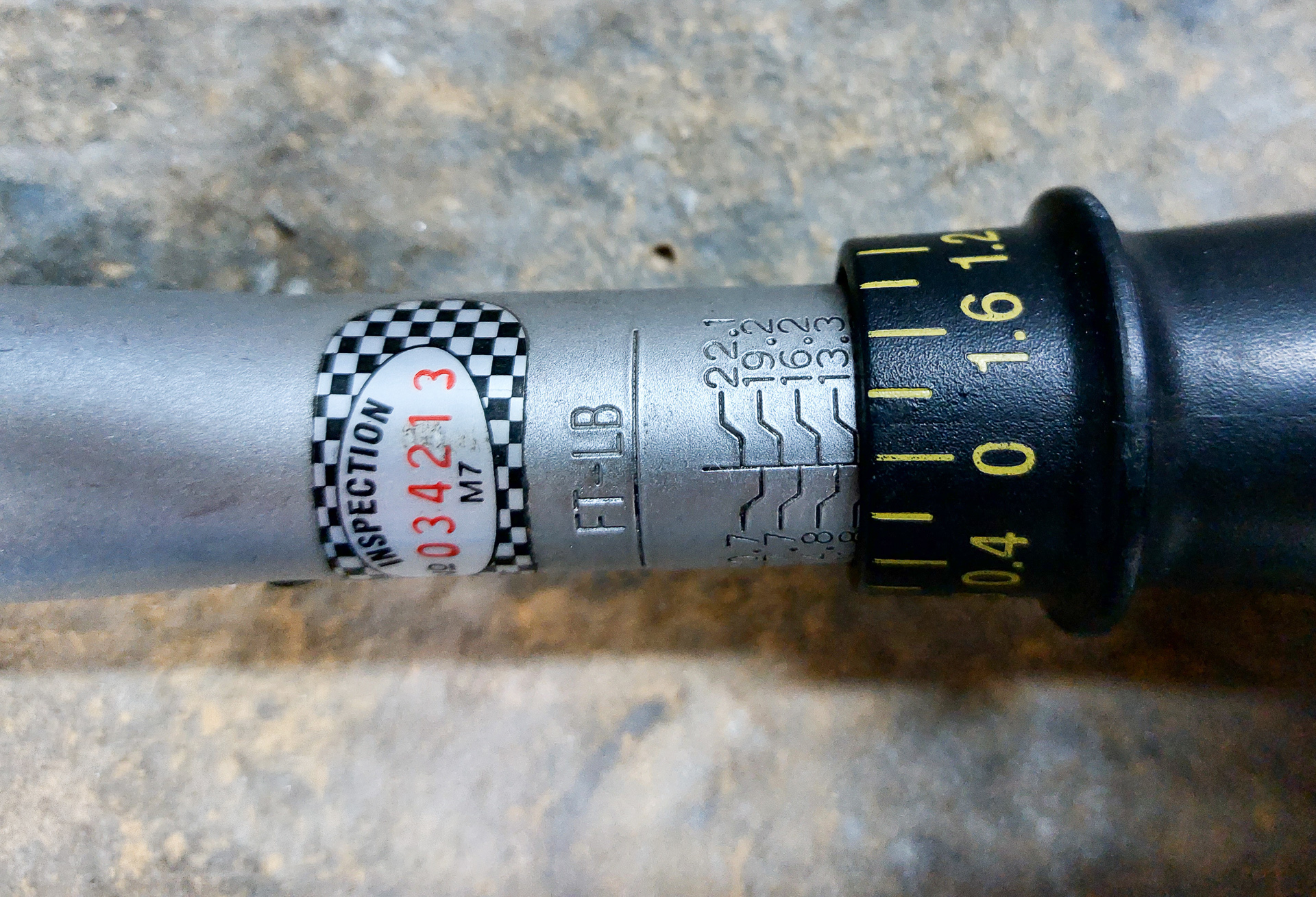
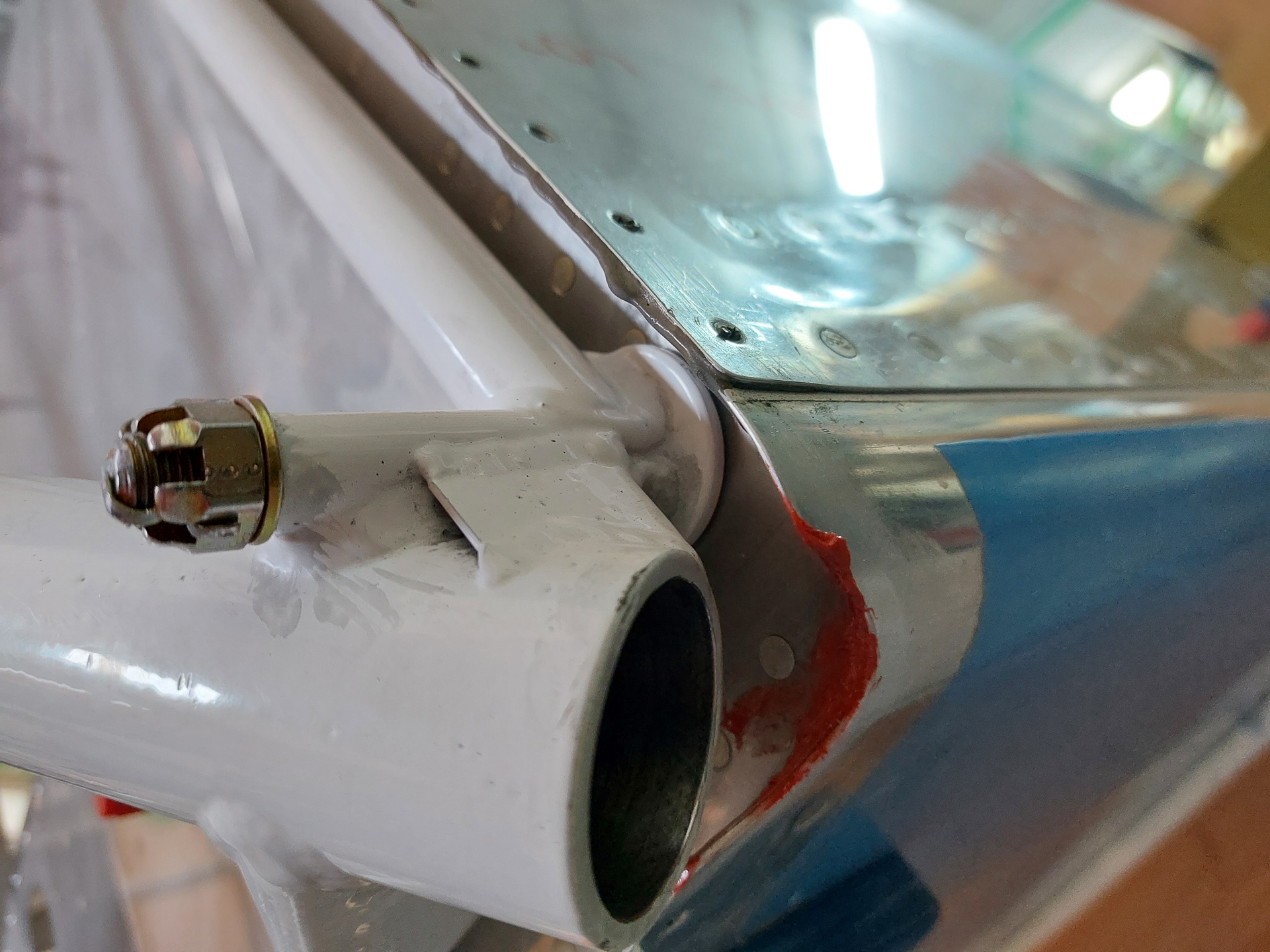
It's never really the right moment to hang the engine mount because there's possibly still penetration holes to make later but you 'll only find those ideal spots when the engine is hanging. And no way to hang the engine without a mount. So I figured I had postponed this long enough in order to hang the engine mount. I have also been put the fuselage on it's gear and final installation of the engine mount has to be completed first. Just to clarify, I already had drilled the firewall attach holes a long time ago, so this workday was about final hanging, re-measuring and torqueing the castle nuts with final cotter pin installation. It's a simple process but I found it a big deal as it's the part that will finally enable the start of the gear and engine ffw work. The firewall is attached with AN6 bolts and AN310-6 castle nuts. My smaller torque wrench that only goes up to 150 in/lbs was unsuitable for these so I had to use another larger scale torque wrench. Torque range on these bolts is 160-190 in/lbs. They are fastened with a castle nut and cotter pin. The procedure on these is to torque to minimum value and then thighten till the next castle notch comes available that aligns with the hole. My torque wrench was with ft/lbs and it's a simple conversion of dividing in/lbs by 12 to get the right ft/lbs number. The range here had to be 13.33-15.83 ft/lbs. The image below shows my wrench set to 13.3 for initial torque.
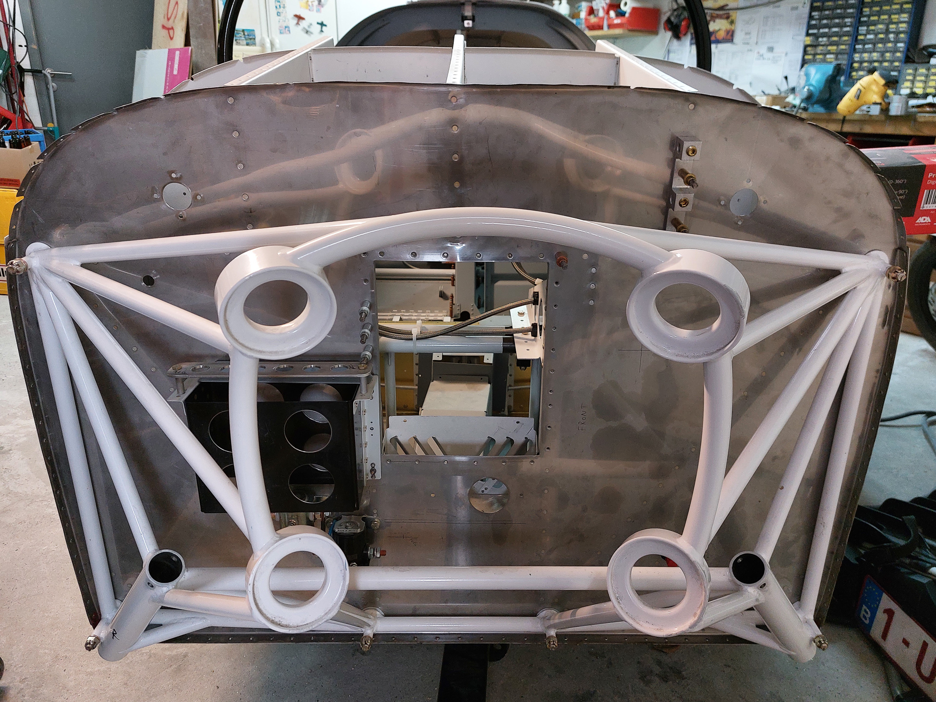
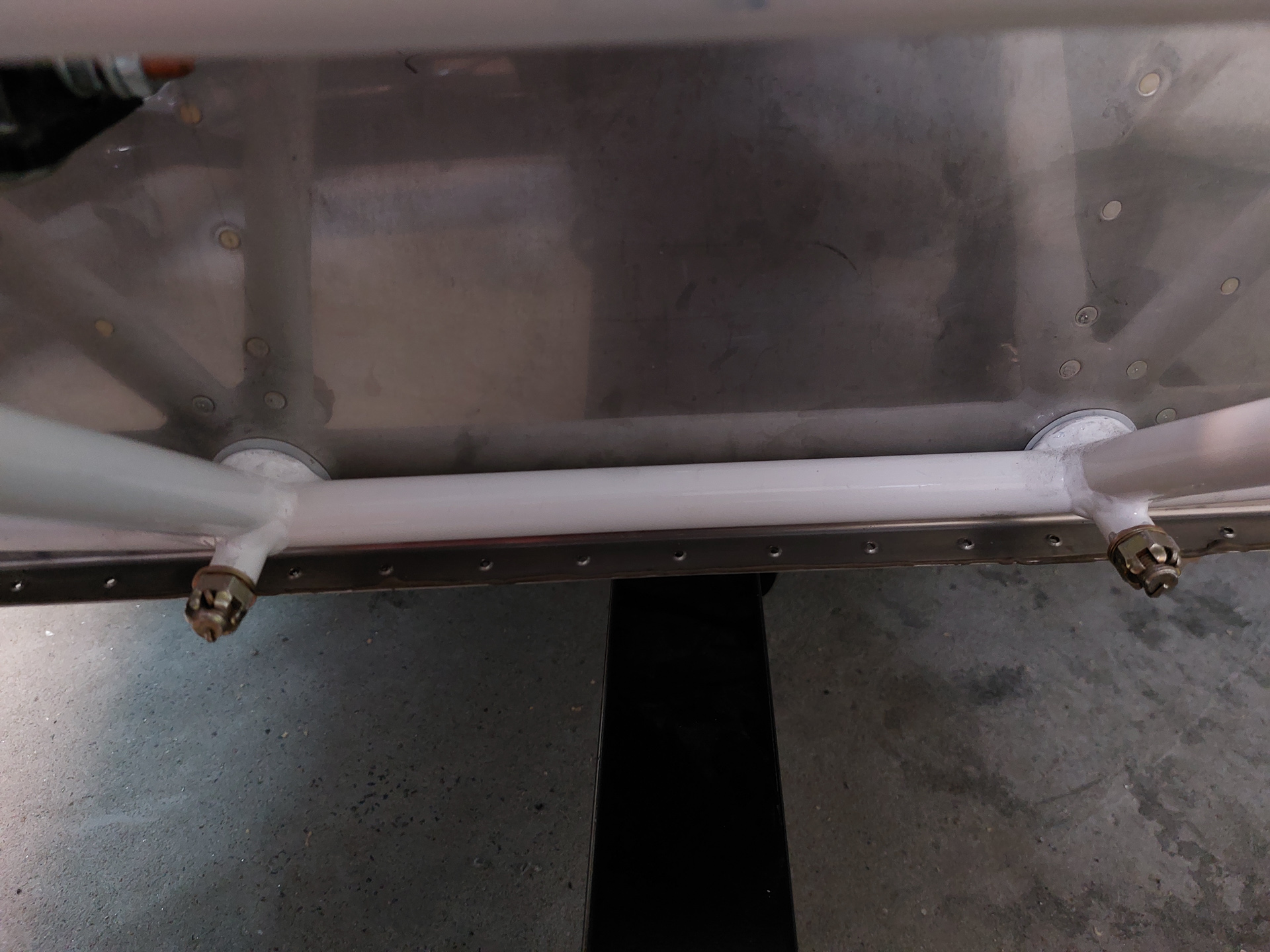
The next image shows all 6 bolts installed with 2 spacers between the mount and firewall at the center bottom.
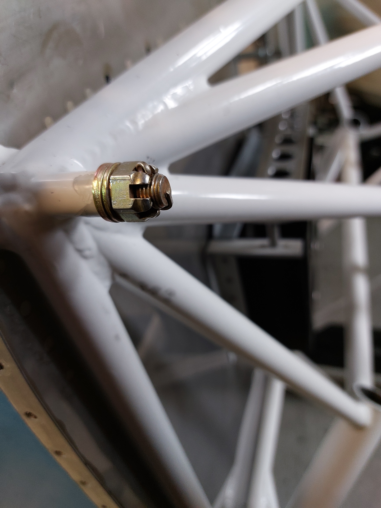
Some detail images of the cotter pin in place. I needed 3 washers on the top pilot side.
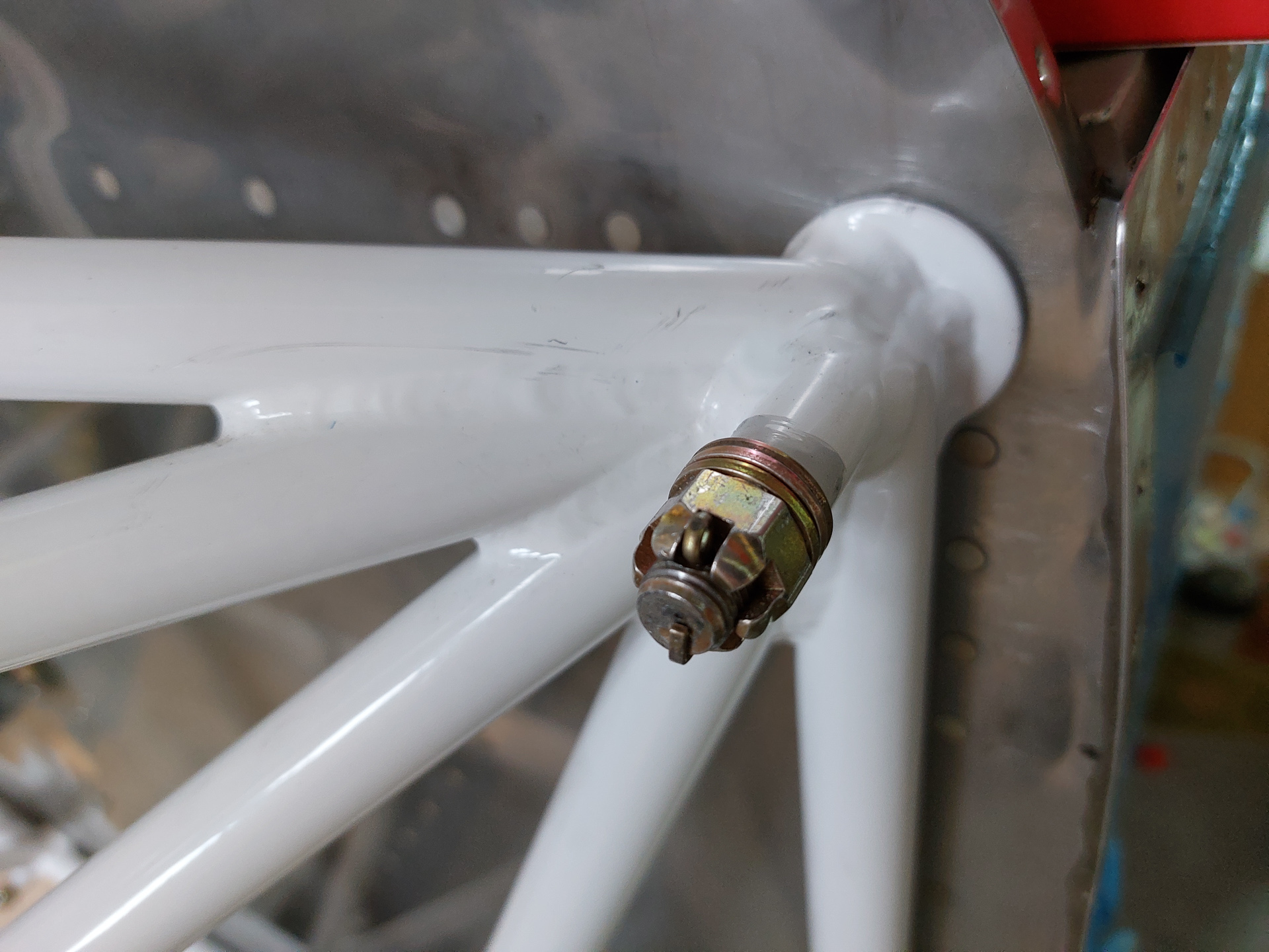
same amount on the top passenger side
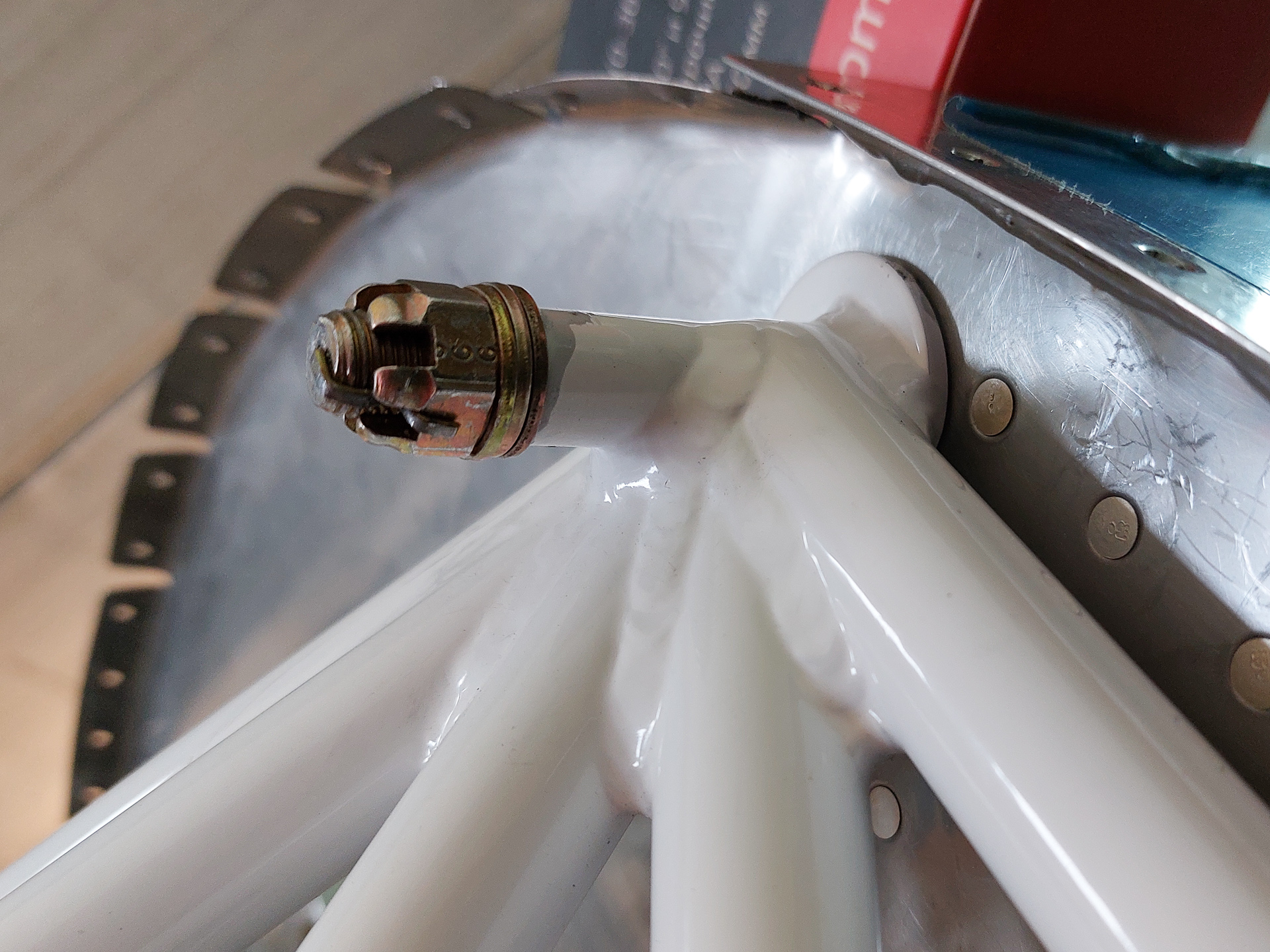
only one was required on the bottom side
Next image shows the spacers and also one washer.
another image of the cotter pin installation.
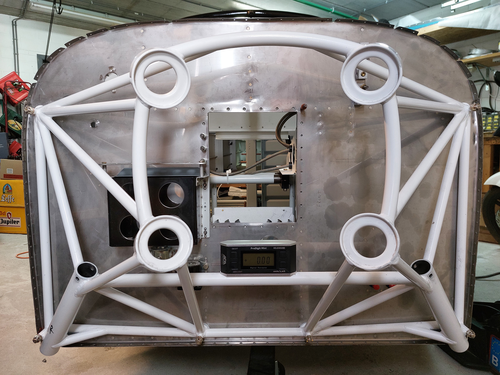
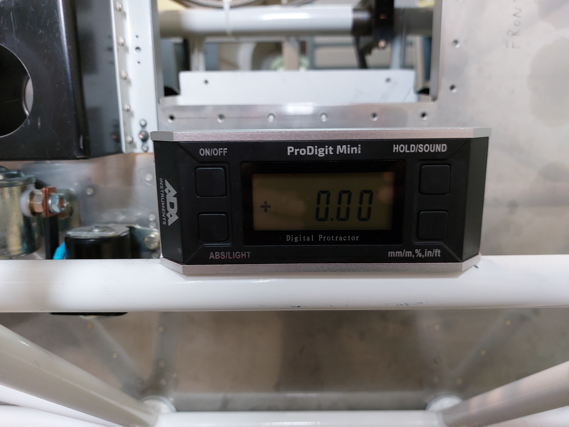
Top view engine mount
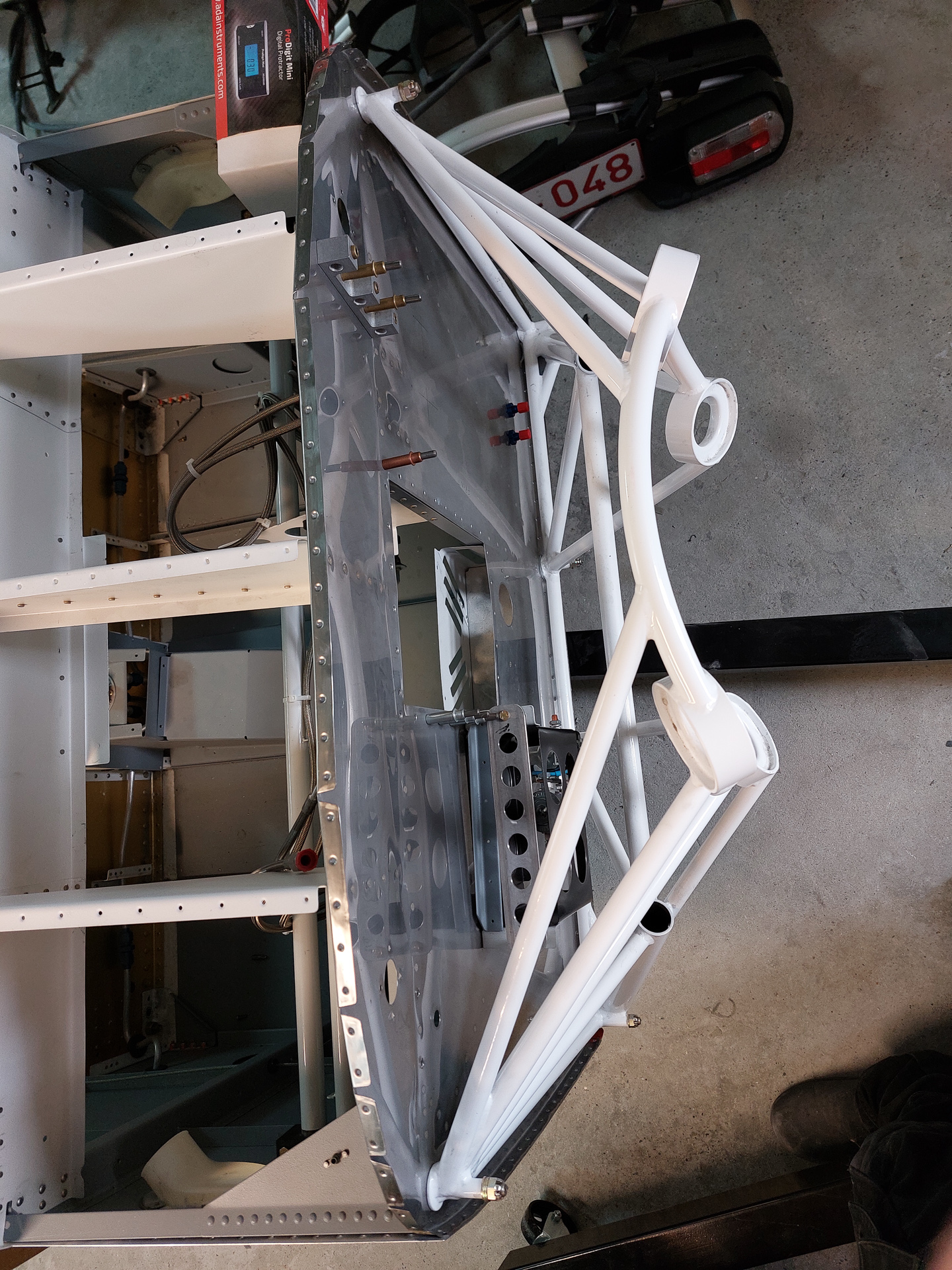
Forward view with the level in place showing a 0.00° level mount.
18/03/2023 - Firewall Passthrough - 3h30
In final preparation before hanging the engine mount, I had to think of the remaininng firewall forward plate work.
One of the things missing were the firewall passthrough holes for electrical wiring on both left and right side.
The left/passenger side hole will be used to pass the battery cable to the vpx and master switch etc. The right side will host engine monitoring cabling.
There are no location specifications on the plans but found the dimensions as shown in the picture from Bruce's website. 2 inch from the top angle and 2" 9/16 from the top rib. I did the same on both sides.

Drilling through stainless steel firewall is a pain. The firewall plate is mounded so no way to use a drill press. I figured the best way would be to have the back supported by a clamped big wood block.

Made the first cut on the pilot side with a regular twisted drill bit #40 and then enlarged.

Used a hole cutter to upsize to the larger diameter and deburred carefully. That stailess steel burr will cut through your finger like a knife goes through warm butter.

I then centered the safe air pass through kit parts in the hole and taped it with good old duct tape to drill the holes for the 4 screw that hold the part in place.

Deburred holes and all done.

Same precedure on the passenger side. Next image is just after being through with the hole cutter.

attach holes drilled (not deburred) and temporarily fitting the passthrough ring.

All looking neat and clean. This will finally be installed when my 3M firebarrier paste arrives so that I can finally screw this in place.

Forward look of the firewall so far with the two holes finished

05/12/2021 - installing transducer manifold - 2h
Some more small tasks on the firewall forward installation.
Located the position for the transducer manifold. This is the small aluminum block that allows to plug lines and sensors. It's used to measure fuel pressure, oil pressure and manifold pressure and is located on the opposite side of the pilot side rib using and enlarging the existing holes.
![]()
I also started surfing a bit for a good location for the firewall penetration of the sensor wires and other electrics and came up with this image found on another builders website.
![]()
Enlarged the first hole #12 which is in common use with the F-7108-L rib. This is the center hole on the rib and the top hole in the transducer.
Then centered the transducer and drilled the other holes for AN3-5A Bolts as per the plans (VA-168 installation on OP-32).
![]()
15-12-2021 - Solenoids and diodes
Had some fun installing the starter and master solenoid to the firewall.

Made a copper bar connection between the common posts and shrinked some shrink tube over it to insulate.
Also installed the 2 diodes which had been hanging around in the shop for a while. They are better of on the plan than losing them somewhere in the hardware stock.
How to use
Use the kit buttons in the top ribbon bar to see a chronological overview per sub section per kit. For the full chronological article list, see chronological build link in prelude menu here below. The easiest way to lookup information is by typing in some part numbers or keywords using the search option in the ribbon bar
Caution !
Some advice on reading my log for fellow builders !
In some articles, I made corrections at later date on the original article to rectify my own stupidities or faults. Read through the entire article if you intend to use my findings/experiences on your own project !
Other content
Social Networking
Legal Mumbo-Jumbo
It’s possible (not likely) that I’m not as smart as I think I am. (Occasionally, I have moments when I know this to be true. Fortunately, the feeling passes quickly.) Although I have tried to make this information as accurate as I can, it is not only possible, but also quite likely, that erroneous and misguided information lurks within these pages. I cannot and do not warrant these pages to be error free and correct. Furthermore, I accept no liability for the use of this (mis)information. And, as many would say, your mileage may vary. If, after reading this, you are intent on proceeding, please be aware that the contents of this site are protected by copyright (copyright © 2011 and 2012). Nonetheless, you may copy this material subject to these two conditions: (1) any information used is for non-commercial purposes, and (2) the source of the material is properly credited. Of course, you may link to any page herein. At some articles, snippets of the plans from Vans are visible. These are for educational and illustrations purposes only and should never be used as plans for part construction or assembly as plans may have changed since the picture was taken and more important they are protected by Copyright by the Vans Aircraft Mothership company.